


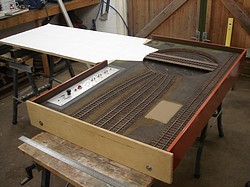

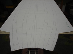
19th December 2008: Work on the Locomotive Yard has started by planning the track layout.


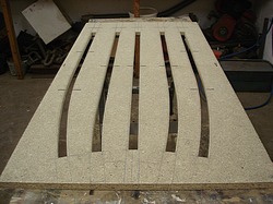
22nd December 2008: Ballast has been removed to make way for the new loco roads leading from the turntable. The old control panel has been stripped out, and the alignments of the roads have been marked out accurately on the new board for the ash pits to be cut out.
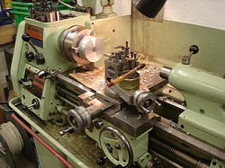


23rd December 2008: The main bearing housing for the turntable has been turned up on the lathe, and the construction of the new baseboard is nearly complete.


24th December 2008: The main bearing housing for the turntable is finished, and the construction of the new baseboard is complete.


27th December 2008: The first photo shows the finished components of the turntable centre bearing, with the first ball race pressed in. The second photo shows the centre bearing assembled. The third photo shows the bearing installed in the board. The fourth photo shows the drive plate located on the centre bearing. The fifth, sixth, and seventh photos show the underneath of the turntable being machined away to receive a brass plate that will fit onto the drive plate. Although the turntable driving mechanism, bearing and drive plate will all be permanently fixed to the board, the turntable itself will be removable for safe transport. Thus, the turntable will be lifted on and off the driving plate. The final photo shows the new board in its first coat of undercoat.


28th December 2008: Pictures one and two show the drive plate and the turntable plate having a very accurate hole at each end of the plates machined with an off-set boring head. The holes in the turntable plate have received brass driving pins (as seen in the fourth photo). These pins transfer the drive from the drive plate, which will be powered by a motor, to the turntable plate which will be attached to the turntable. Therefore when the turntable is lowered into place on the drive plate, these driving pins fit into the two holes in the drive plate (as seen in the third picture) and accurately locate the turntable in the correct position. The two pointed pins in the drive plate are to approximately align the turntable when the turntable is being put on. Lastly the new control panel has been cut out and the component holes drilled out.
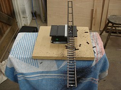


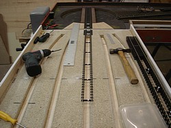

29th December 2008: Sleepers have been cut using a mini circular saw to leave just the sleeper chairs for the track over the ash pits. Every eighth sleeper has been left intact in order to act as gauge bars. The first panel of track has been laid on the centre road. Lastly the turntable plate has been attached to the underneath of the turntable.


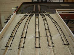

30th December 2008: The first five pictures show the manufacturing of the hub which will secure the indexing plate to the turntable shaft. The indexing plate will semi-automatically align the turntable to the tracks leading from the turntable. Pictures six and seven show the nearly completed hub. The final two photos show the track laying progress.


31st December 2008: The hub which will secure the indexing plate to the turntable shaft has been completed, and the last of the track laying has been finished.
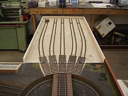
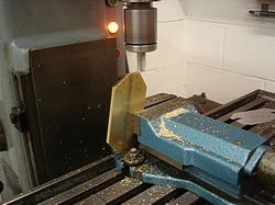

1st January 2009: The finishing touches to the track, such as cutting the track circuit gaps in the rails and removing the sleepers which were acting as gauge bars, have been completed. The four roads without buffer stops will lead into the front 4 inches of a loco shed at the very far end of the board. The fifth road with the buffer stop is shorter to allow room for a small lean-to on the side of the loco shed. The last two photos show the two plates which carry the turntable on its rollers.


2nd January 2009: Work on the two plates which carry the turntable on its rollers continues, and the new board has been painted in gloss white on its underneath.


3rd January 2009: The four printed circuit boards required for wiring up the new board have been cut out and jig drilled to receive the various components. The rollers to carry the turntable have been made and fitted to the turntable.


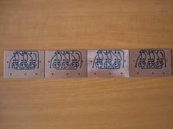


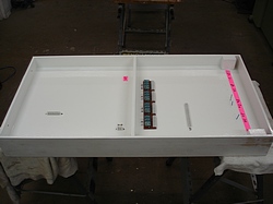
4th January 2009: The first two pictures show the sprung pickups have been made and fitted to each end of the turntable. The four printed circuit boards (PCBs) required for wiring up the new board have been made; the third photo shows the tracks marked out in etch-resistant ink, the fourth photo shows the etching, and the fifth photo shows the completed PCBs with the components attached. The last photo shows the components attached in position on the underneath of the board ready for wiring up.
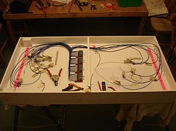
6th January 2009: The wiring on the new board has been started.


7th January 2009: The wiring on the new board has continued, and the main structure of the loco shed is shown in place.

8th January 2009: The wiring on the new board is now finished except for the jumper cables to the turntable board and the control panel which will be added later on.


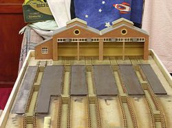
11th January 2009: The engine shed is almost complete and ready for painting.


14th January 2009: The protective cover board for the relay units on the new board has been made. The second photo shows the mounting holes being drilled in the drive plate to attach it to the hub. The third photo shows the drive plate being routed circular. The fourth photo shows the mounting bracket for the drive shaft bearing being machined. The last two photos show the drive shaft mounted in the bearing and able to drive the drive plate which has been secured to the turntable driveshaft.

28th January 2009: The loco shed has been painted, and work on the loco yard scenery has started.

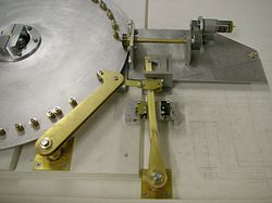
29th January 2009: Work continues on the turntable; the drive from the motor to the drive plate has been completed. The mechanism seen at the bottom of the second photo is the means by which the turntable will semi-automatically align itself to the tracks leading from the turntable and then lock in position. The left-hand arm will be withdrawn clear of the brass locating pins attached to the drive plate when the turntable is rotating. When the turntable is roughly in line with the track leading to it, the arm will be driven inwards by a second motor. As the arm moves inwards, the roller bearing on the end of the arm will engage accurately between two of the brass location pins, thereby accurately aligning the turntable and locking it in position. The arm is then withdrawn before the turntable next rotates.
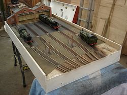


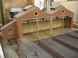
6th February 2009: Work on the loco yard scenery continues.


7th February 2009: The control panel for the new board has been made and wired up, and the printed circuit boards that will control the turntable have been made.


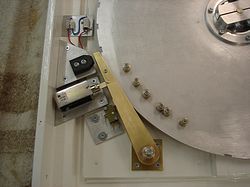
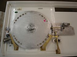
8th February 2009: The jumper cable to the control panel for the new board has been made and terminated. The second photo shows the new control panel in place. The leg to carry the new board has been made. In the fourth photo, the notches cut in the rim of the indexing plate are detected by a roller in the arm, which operates a micro switch. The operation of the micro switch, stops the rotation of the turntable and permits the locking arm to accurately align and lock the turntable.


9th February 2009: The jumper cable to the turntable board from the new board has been made and terminated. The controls have been labelled on the new control panel for the turntable board, and it has then been painted with gloss varnish. The controls have been fitted, and it is now ready for wiring up.

10th February 2009: Wiring work on the new control panel has been started.


11th February 2009: Wiring work on the new control panel has been finished apart from the last of the wires which need terminating in the block connectors. The control panel has been fixed to the base board.
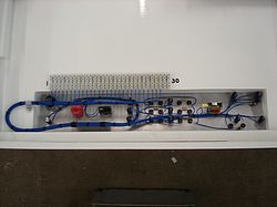


12th February 2009: The last of the wires from the control panel have been terminated in the block connectors. The motor drive to the locking arm has been manufactured and fitted. Lastly, minor wiring alterations to the board adjacent to the turntable board have been carried out.


13th February 2009: Finishing touches to the turntable operating equipment have been completed, and the printed circuit boards have been positioned and secured, meaning that the board now only requires wiring up. A new connecting cable to the adjacent board has been installed.
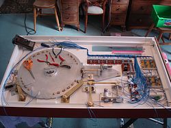
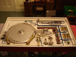
15th February 2009: The turntable board has been wired up and tested. No faults were found with either the wiring or the turntable operating mechanism.


16th February 2009: The whole of the station-end of the layout was set up for a full functional test of the new equipment and wiring. The design is very successful and works correctly.


22nd February 2009: A protective cover board has been made for the turntable board to protect the turntable operating mechanism and the relay units. A protective cover board has also been made to protect the scenery on the new loco yard board.


3rd March 2009: Over the last week, the new board and the protective cover board for the turntable operating mechanism have been undercoated and top coated.

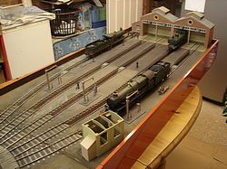


13th March 2009: Work on the scenery is almost complete with just a few more figures to be painted, and the sand drying furnace to be finished.
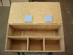

23rd March 2009: A transport box is being made for the removable items of scenery.


26th March 2009: The sand drying furnace has been finished together with the remaining figures. The scenery transport box has also been completed.

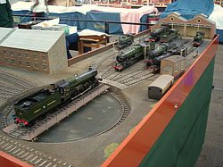
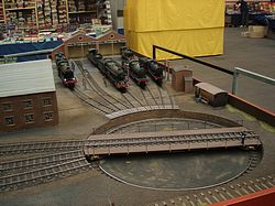
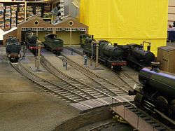
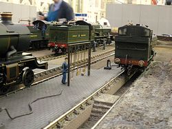
29th March 2009: The completed Loco Yard was displayed at its first exhibition at The London Festival of Railway Modelling at Alexandra Palace in March 2009.